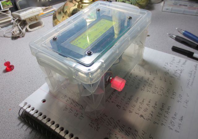
Completed Power Box
I recently constructed a portable power pack that would serve a dual role: operating our telescopes during observing sessions and running my ham equipment on camping trips. By coincidence, ham radio transceivers and telescopes have similar power requirements (12V @ 1-10 A). Most amateur astronomers use either car or motorcycle batteries, auto JumpStart devices or expensive power packs sold by telescope manufacturers. 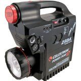
The power packs sold by telescopes manufacturers are basically automotive jump starters having one or more female cigarette lighter plugs that are used to power the telescope and accessories. Not only are these power packs expensive they sometimes do not have enough capacity to run a telescope and dew heaters for a whole night of observing in the humid midwest.
Motor cycle and automotive batteries have sufficient capacity, but pose a significant safety risk when stored and charged indoors. A safer alternative is the sealed AGM lead acid battery often used to power security systems and uninterrupted power supplies (UPS). After a bit of research I determined that a 28 amp-hr AGM (absorbed glass mat) battery would provide enough energy to power our telescope for a weekend of observing and that the same battery would easily power my Elecraft KX3 for several days of QRP operation.
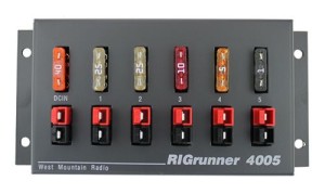
I made the decision to utilize Anderson Power Poles for connections because of the reliability and flexibility they provide. I purchased a RigRunner Power Pole panel to provide a connection point for the telescope and its accessories.
For a case, I considered the Pelican cases, but was turned off by their high price and weight. I didn’t need a case that was 100% waterproof or one that could survive the airport baggage handler gorillas. I considered using an RV battery box, but they are awkward to handle. While walking through the Walmart fishing section the other day I stumbled across the perfect box or my application. It is made by Flambeau Outdoors. It is ( 15″W x 9″H x 8″D ), water tight, has a strong handle, a hinged top and a large lockable latch. The box was large enough to hold the 28 Ah battery, charger and the charger power cord. There was some room left over to hold other accessories: female cigarette lighter plug to power pole adapter, a power pole Ah meter, spare fuses and a power pole extension cable.
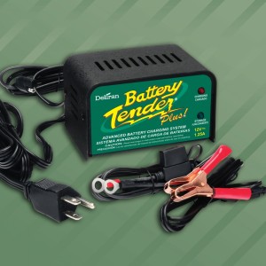
I used a Battery Tender Plus 1.25 A charger to charge the battery. These chargers are the ultimate trickle chargers for lead acid and AGM batteries. They have a number of features:
- Temperature compensated to ensure optimum charge voltage according to ambient temperature.
- Automatically switches from full charge to float charging mode.
- Battery Tender® at 1.25 amps will charge as fast or faster than any 3 amp charger available.
- Reverse Polarity Protection to ensure user safety. Red & Green Lights Alternately Flash in this condition.
- Complete 4-step charging program (Initialization, Bulk Charge, Absorption Mode, Float Mode).
Completed Power Box
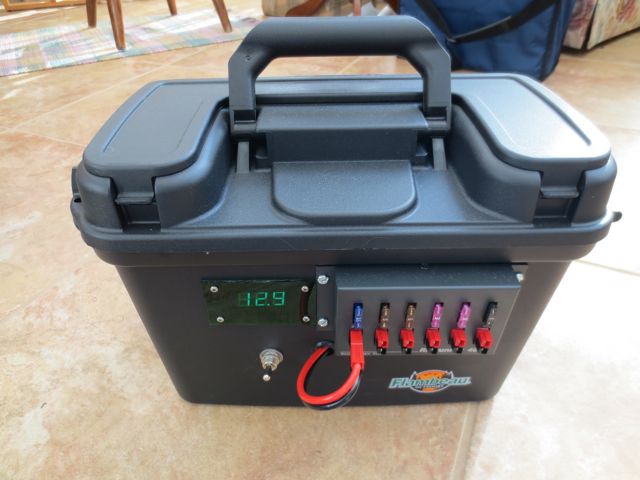
Here are some photos of the finished power pack. The first photo is of the exterior of the power pack. Some of the features are the integral voltmeter which shows the current state of the battery charge. The case has a very strong handle which is important because the finished power pack weighs in at nearly 25 lbs. I incorporated a three position switch which selects the Operate, Off and Charge positions. During Charging I the switch disconnects the Power Pole panel from the battery to eliminate any chance that a failure of the charger could result in a over voltage condition on the Power Pole panel.
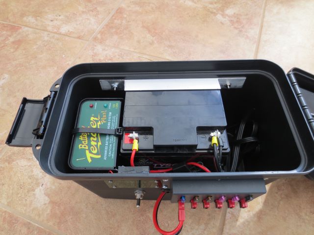
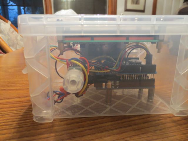
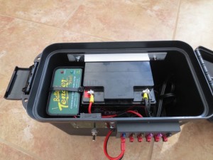 The next photo shows the interior of the Power Pack. The battery is a 28 Ah AGM battery. The Battery Tender charge is attached to a Aluminum “L” bracket with a heavy duty wire tie. I used the “L” bracket to support the Battery Tender for two reasons: so that it was flush with the top of the case so that it is easier to see the charger LEDs and to provide a space below the charger where I could wire tie the extra Battery Tender wiring. The AGM battery is held in place by 4 pieces of Aluminum “L” channel (3 around the base of the battery and one which captures the batter at the top. The brackets hold the battery snuggly against the back of the case. All of the fasteners are stainless. I also placed 4 rubber feet on the bottom of the case so that the fasteners inserted into the bottom of the box would not scratch any surface the box is placed on during storage.
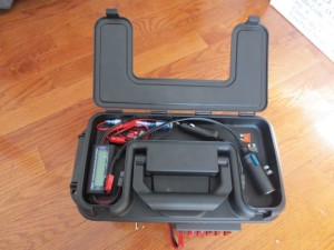
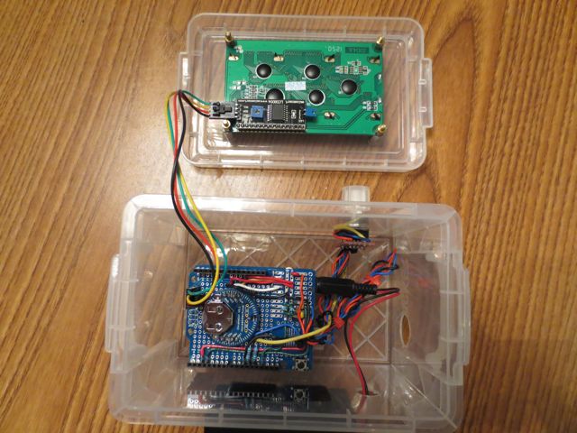
This photo shows the small compartment in the top of the power pack case which can be used to store cables, spare fuses and the Volt/Amp/Watt-Hr meter I use to check each device I connect to the power pack.
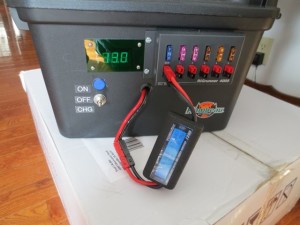
Power Pack with Amp-hr Meter attached
The Amp-hr meter can also be used to monitor the total Amp-hrs consumed from the battery by placing it inline between the input to the RigRunner and the Power Pole connection coming from the battery (shown at right).
After building the first power pack I have since built two additional power packs–one for a friend and another to run my wife’s Celestron telescope. I think my Power Pack will also see a lot of use running my new KX3 on summer camping trips.
Best 73,
Fred