Elecraft KX3 on the Way

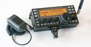
Elecraft KX3

Elecraft KX3

After finding myself spending more and more time operating CW I decided to add an Elecraft KX3 to my shack.  My first exposure to the KX3 was at the Bedford, IN hamfest this fall.  Since then I have spent several hours reading the many glowing reviews of this rig on eHam.com.  I also downloaded the manual from the Elecraft site and spent a several more hours studying the manual.

I decided to purchase the KX3 pre-assembled with the internal antenna tuner.  I decided not to build the kit version because for me the mechanical portion of the assembly of my K2 was the least enjoyable part of assembling the kit.  Since the KX3 kit is only mechanical assembly, I decided to just go ahead and purchase it pre-assembled.  Unfortunately I will not have the KX3 in time for this weekends 10m contest which promises to have outstanding propagation (SFI 160+).

I should have the new rig in a few days and will post my initial observations.   Later I plan to put together a more thorough review of the rig.

73,

Fred

Homebrew Portable Power Pack

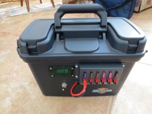
Completed Power Box

Completed Power Box

I recently constructed a portable power pack that would serve a dual role: operating our telescopes during observing sessions and running my ham equipment on camping trips.  By coincidence, ham radio transceivers and telescopes have similar power requirements (12V @ 1-10 A).  Most amateur astronomers use either car or motorcycle batteries, auto JumpStart devices or expensive power packs sold by telescope manufacturers.  CelestronPowerPack
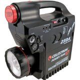
The power packs sold by telescopes manufacturers are basically automotive jump starters having one or more female cigarette lighter plugs that are used to power the telescope and accessories.  Not only are these power packs expensive they sometimes  do not have enough capacity to run a telescope and dew heaters for a whole night of observing in the humid midwest.

Motor cycle and automotive batteries have sufficient capacity, but pose a significant safety risk when stored and charged indoors.  A safer alternative is the sealed AGM lead acid battery often used to power security systems and uninterrupted power supplies (UPS).   After a bit of research I determined that a 28 amp-hr AGM (absorbed glass mat) battery would provide enough energy to power our telescope for a weekend of observing and that the same battery would easily power my Elecraft KX3 for several days of QRP operation.
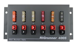
RigRunner4005

I made the decision to utilize Anderson Power Poles for connections because of the reliability and flexibility they provide. I purchased a RigRunner Power Pole panel to provide a connection point for the telescope and its accessories.

For a case, I considered the Pelican cases, but was turned off by their high price and weight.  I didn’t need a case that was 100% waterproof or one that could survive the airport baggage handler gorillas.  I considered using an RV battery box, but they are awkward to handle.  While walking through the Walmart fishing section the other day I stumbled across the perfect box or my application.  It is made by Flambeau Outdoors.  It is  ( 15″W x 9″H  x 8″D  ),  water tight, has a strong handle, a hinged top and a large lockable latch.  The box was large enough to hold the 28 Ah battery, charger and the charger power cord.  There was some room left over to hold other accessories: female cigarette lighter plug to power pole adapter, a power pole Ah meter, spare fuses and a power pole extension cable.
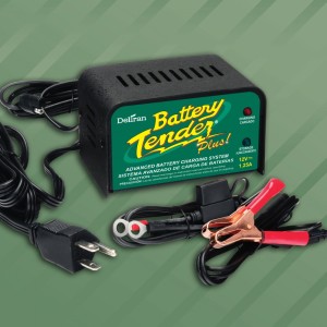
BatteryTender

I used a Battery Tender Plus 1.25 A charger to charge the battery.   These chargers are the ultimate trickle chargers for lead acid and AGM batteries.  They have a number of features:

  • Temperature compensated to ensure optimum charge voltage according to ambient temperature.
  • Automatically switches from full charge to float charging mode.
  • Battery Tender® at 1.25 amps will charge as fast or faster than any 3 amp charger available.
  • Reverse Polarity Protection to ensure user safety. Red & Green Lights Alternately Flash in this condition.
  • Complete 4-step charging program (Initialization, Bulk Charge, Absorption Mode, Float Mode).
Completed Power Box

Completed Power Box

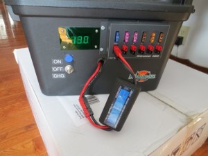
Here are some photos of the finished power pack.  The first photo is of the exterior of the power pack.  Some of the features are the integral voltmeter which shows the current state of the battery charge.  The case has a very strong handle which is important because the finished power pack weighs in at nearly 25 lbs.  I incorporated a three position switch which selects the Operate, Off and Charge positions.  During Charging I the switch disconnects the Power Pole panel from the battery to eliminate any chance that  a failure of the charger could result in a over voltage condition on the Power Pole panel.
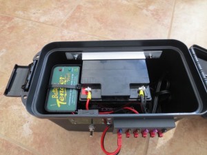
IMG_0435The next photo shows the interior of the Power Pack.  The battery is a 28 Ah AGM battery.  The         Battery Tender charge is attached to a Aluminum “L” bracket with a heavy duty wire tie.  I used the “L” bracket to support the Battery Tender for two reasons: so that it was flush with the top of the case so that it is easier to see the charger LEDs and to provide a space below the charger where I could wire tie the extra Battery Tender wiring.  The AGM battery is held in place by 4 pieces of Aluminum “L” channel (3 around the base of the battery and one which captures the batter at the top.  The brackets hold the battery snuggly against the back of the case.  All of the fasteners are stainless.  I also placed 4 rubber feet on the bottom of the case so that the fasteners inserted into the bottom of the box would not scratch any surface the box is placed on during storage.
IMG_0437


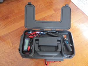
This photo shows the small compartment in the top of the power pack case which can be used to store cables, spare fuses and the Volt/Amp/Watt-Hr meter I use to check each device I connect to the power pack.


Power Pack with Amp-hr Meter attached

Power Pack with Amp-hr Meter attached


The Amp-hr meter can also be used to monitor the total Amp-hrs consumed from the battery by placing it inline between the input to the RigRunner and the Power Pole connection coming from the battery (shown at right).

After building the first power pack I have since built two additional power packs–one for a friend and another to run my wife’s Celestron telescope.  I think my Power Pack will also see a lot of use running my new KX3 on summer camping trips.

Best 73,

Fred

An Arduino Project for the Link Telescope

IMG_0181

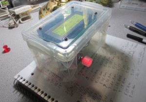
Top view of the Hour Angle Calculator in Operation — note the rotary encoder has an internal RED led.

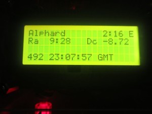
I have been continuing to work with the Arduino single board computers.  One of the tasks required at the Link Observatory is to align the Argo Navis (digital encoders) using two well spaced stars.  My wife and I have found that the easiest way to pinpoint the alignment stars is to use the telescopes German equatorial mounts setting circles. One of the challenges we had using the setting circles was having to continually recalculate the Right Ascension Hour Angle as we are moving the telescope into position–it takes a bit a time to accurately position a 36″ telescope that weighs over a ton.  Therefore we would have to keep recalculating the hour angle which is calculated by subtracting the stars Right Ascension from the current local Sidereal time ( which is obviously changing).

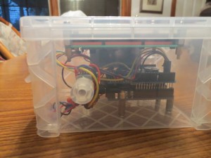
IMG_0178I decided to use an Arduino to continuously calculate the RA Hour Angle using equations to calculate the sidereal time and the Hour Angle given the selected alignment stars Right Ascension.   This project involved building a circuit which included a real time clock, a rotary encoder ( to select the star from a lookup table) and an LCD display.  I assembled the circuit in a plastic 3″ x 5′ card box I found at Office Depot.

One of the more challenging aspects of the design for me was getting the rotary encoder to accurately count.  I used a 24 pulse per rotation encoder which I purchased from Sparkfun (http://sparkfun.com).  In the initial circuit the software would count extra pulses and sometimes miss pulses.  After I tried several different software schemes to resolve the problem I finally used an  oscilloscope to examine the waveforms coming out of the rotary encoder.  Once I attached the scope I immediately saw the problem.  When  the encoder is being rotated It would frequently have high frequency wiping noise on the encoder A and B pins.  After I attached a couple of .01 uf capacitors between the pins and ground the encoder began working flawlessly.

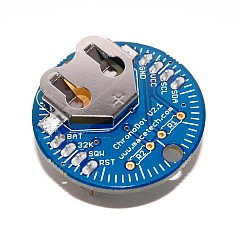
ChronoDot Realtime Clock Module

ChronoDot Realtime Clock Module

The next challenge was to interface a realtime clock to the Arduino.  This turned out to be very easy using a ChronoDot clock module.  This little gem interfaces to the Arduino using the I2C serial interface.  It will run over 8 years on a single battery and will maintain the time with an accuracy 1 minute a year.  The module requires four connections (5V, Gnd, SCL and SDA).  SCL and SDA are the serial interface connections.  The neat thing about the I2C interface is that many devices can share the same interface.  In this project I  also used the I2C interface to interface a 4 line by 20 character display.


IMG_0184I spent quite of bit of time developing the software–mainly because I was also learning how to program in ‘C’ at the same time I was developing the code to for the project.

The software to interface to the realtime clock, rotary encoder and display were developed by modifying examples readily available on the web.

I also had to develop the software to calculate the Sidereal time from GMT using one of several algorithms I found on the web.  One problem I experienced was an error of about 5 to 30 seconds in the Sidereal time because of floating point round off errors in the Arduino software.  This occurs because the  Arduino software does not support double precision floating point calculations.  This did not present a major  problem in my application since the resolution of the mechanical setting circles on the Link Telescope only have a precision of around 1 minute.

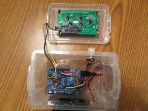
The followingIMG_0187 photo shows the internal circuitry of the Hour Angle Calculator.  The circuit board at the top of the photo is the backside of the 4 line by 20 character display.  The four wires connect the display to power and the I2C interface.  The circuit board shown in the 3 x 5 file card box is the prototyping shield attached to the top of the Arduino.  This board holds the realtime clock, the pull-up resistors and bypass capacitors for the rotary encoder and other wiring to needed to interface to the Arduino.  The circuit can be powered for several hours using a 9V battery.

73,

Fred
Late Winter Storm

Just when I thought Spring was finally arriving, the National Weather Service issued a winter storm warning for the next two days.   We are expecting up to 10″ of snow this afternoon and tonight.  I guess I will just have to stay inside chasing DX and working on the Arduino project I have been putting together for the Link Observatory.  Shucks!!!

I’ll try to post a few photos when the snow arrives–assuming our HughesNet satellite internet does not go out.

73,

Fred
Easter Island

Easter Island Heads

Easter Island Heads

It was pretty exciting being able to work Easter Island.  There is currently a DXpedition operating CW only from the island.  I am not sure how rare of DXCC entity Easter Island is, but it is exotic.  When I think of exotic places, Easter Island is near the top of my list.

I hope everyones gets the opportunity to bag this one.  The British operators are doing a fantastic job controlling the pileup.

73,

Fred
Meteor Over Russia

A large meteor caught on video over Russia.  Here is one of the videos that have been posted on YouTube.

Here is a good article about the meteor.  Phil Plait’s Bad Astronomy blog discusses the meteor that came down in Russia in this article: Bad Astronomy Blog.

I hope some Russian hams were able to operate some Meteor Scatter propagation on VHF.

73,

Fred
My First Tower (Part 6)

After a year of planning and preparation it was finally time to install the tower.  The previous 5  articles focused on the preparations that led up to installation day.

Crane Lifting Tower

Crane Lifting Tower

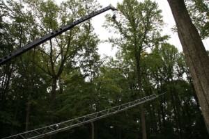
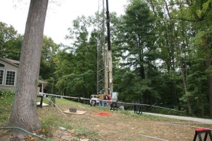
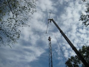
Don, K4ZA, would be using a crane for the tower installation.  The first step was to lift the assembled tower into position and bolt it to the concrete base.  This took a fairly tall crane because the tower was 70′ tall and the crane was sitting nearly 10′ lower than the tower base.  Don selected a 100′ crane with an additional 20′ Jib. Fortunately the crane operator did not have install the jib because that would have added a couple of hours to the time onsite.  The photo at the right shows the crane beginning to lift the tower.

Tower Being Positioned Over Base

Tower Being Positioned Over Base


Once the tower was fully vertical, the crane operator eased it over the concrete base so that the ground crew could attach the tower to the Trylon base section.


BoltingTowerToBase


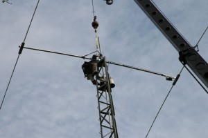
Once the tower was aligned to the base, twelve bolts were used to attach it to the base.  Once the tower was secured to the base Don climbed up the tower to begin the installation of the antennas.

The procedure to install the antennas involved installing the highest antenna first, followed by the next highest and finally installation of the lowest antenna.  After each antenna was attached to the mast, the mast was raised using a come-along which had been attached between the lower portion of the chrome-molly mast and the top thrust bearing plate at the top of the tower.

Lifting XM-240

Lifting XM-240


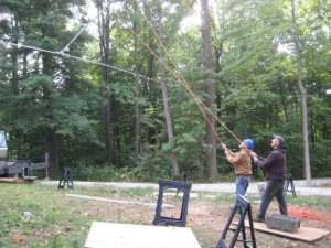
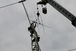
Since highest antenna was the small Cushcraft 2m, 6m and 70cm antenna it was decided it would be easier to install the XM-240B (2 element 40m beam) first.  The photo to the right shows  the ground crew guiding the 40m beam as the crane operator lifted it to Don.  Our job was to keep it properly aligned so that Don could pull it to the mast and an install the U bolts.


XM-240 Being Lifted Into Position by the Crane

XM-240 Being Lifted Into Position by the Crane


The next two photos show the 40m beam being lifted into position and Don attaching the beam to the mast.


Attachment of the 40m Beam to Mast

Attachment of the 40m Beam to the Mast


Installing 2m, 6m and 70cm Beam

Installing 2m, 6m and 70cm Beam


Once the 40m beam was in place, the small Cushcraft beam was attached above the 40m beam.


Installing M2 10-30 LP8

Installing M2 10-30 LP8

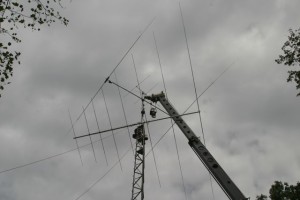
The final antenna we lifted was the monster 8 element 10-30 mHz M2 log periodic.  The log periodic has a 30 foot boom and a maximum element length of 55 ft.  We experienced a lot of excitement lifting this antenna because one of the elements slipped behind the chain on the crane boom when it got hit by a gust of wind.  It took several minutes to maneuver the beam out of the chain.  I think my heart stopped for a few seconds until the LP8 popped out of the crane chain.

Settling up with the Crane Operator

Settling up with the Crane Operator


After all of the antennas had been attached to the mast it was time to pay the crane operator and get him on his way.  Time is literally money when you are dealing with cranes.


After the crane work was completed Don spent a couple more hours finishing the antenna and rotor installation.    The Heliax, rotor cable and weather proofing of all of the connectors were completed the next day.

Completed Tower

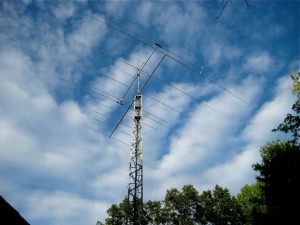
Completed Tower and Antennas


After everything was done we celebrated with a nice steak dinner!

73,

Fred
 

Evening in Shack

I spent the evening in the shack catching up on QSLing.  I had a stack of cards I have received that needed to be marked as confirmed in my logbook.  I also have a large stack of bureau cards that I also need to mark as confirmed in DXLab.  However the bureau cards take a quit a bit longer because many of them are requesting return cards which need to be queued and processed using Global QSL.  The process involves preparing an ADIF file which I upload to Global QSL.  After asking a few questions the cards are printed and sent to the appropriate bureau.  I generally do not use the bureau when I really need a return card.  Many DX stations and QSL managers do not respond to bureau cards.  I always verify the QSL route through QRZ.com or the DX news letters before I send a card.  My return rate on bureau cards is probably less than 20%.  My QSL rate with LoTW is over 40%.  My return rate on direct QSLs with SAE and green stands is well over 80% so far.  OQRS seems to be the best way to QSL if your willing to invest the $2-4 for the card.  Of course that is a reasonable cost when compared to the cost of a QSL I mail via international air mail with $2 of green stamps.  I have had a 100% return rate on OQRS cards thus far.  While i worked on the QSLs I listened to the bands and worked a little DX.

The next thing I did was start the process of upgrading the hard drive in my shack computer to a Solid State Drive.  I installed the new drive but I put off the cloning of my C drive to the new drive until tomorrow since I wanted to clean up my C drive and defrag it before cloning the data to the new SSD.  The SSD should significantly boost the responsiveness of my computer; especially when running N1MM.  I’ll report on the improvement once I complete the upgrade.

73,

Fred

My First Tower (Part 5)

Base After Final Grade

Base After Final Grade


After the tower base was completed it had to cure for at least 30 days before the tower could be installed.  In my case that was not a problem, because the tower based was allowed to cure for about 6 weeks while I waited for one of the antennas and a few remaining hardware items to arrive.

Finally by mid September  everything had arrived.  It was now time for the big event.  Don said that I should plan on a full week for the installation because several things had to be completed during that week prior to erecting the tower and antennas.   Some of the major items that had to be completed were:

  1. Construct the three antennas and position them on the ground where they could be picked by the crane.
  2. Cut and terminate the 5 runs of Heliax that would be going up the tower
  3. Bolt the 7 tower sections together and install the step bolts up one  side of the tower.
  4. Fabricate and install a stronger rotor plate, and an additional thrust bearing plate.
  5. Construction of  the tower control box which holds the lightning protection and antenna switching.
  6. Construct the coax jumper loops which connect each antenna to its corresponding Heliax.
  7. Install the two thrust bearings on the tower
  8. Anchor the antenna mast inside the tower and install a large anchor at the top of he tower so that a come-along can be used the raise the mast as antennas are installed.
  9. Do a final check on the rotor before lifting the tower.
  10. Weather proof all connections on the antennas
  11. Tripple check every item that will be installed on the tower, including: antennas, rotor, bearings, rotor cable etc.  It is much easier to fix an item when it is sitting on the ground than once it is 70′ in the air.

This list shows the major items that had to be completed before the tower could be installed.  I left out a few of the items; including a half dozen trips to the hardware store to pickup a few odds and ends including over 20 saw horses to hold the antennas during assembly.

Assembly of M2 10-30LP8

Assembly of M2 10-30LP8

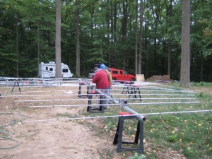
Assembly of the antennas was a much bigger job than I had anticipated.  One of the first steps is to find an area big enough to build two large beams so that they can be picked up by the crane.

This was not an easy task since there were still a number of large trees remaining in the backyard.

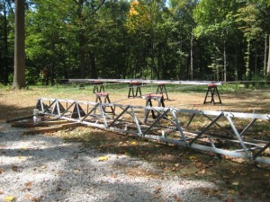
We started with the M2 10-30 LP8 which has a 30 ft boom and 8 elements with the longest being 55 feet tip-to-tip.  It is important to carefully read and follow the instructions and re-check all the work at least two times.  A final step was to check the antenna with an antenna analyzer (MFJ-259B) to make sure it was performing like an antenna (low SWR an resonant at all the right frequencies).  The  assembly of the LP8 took 1-1/2 long days.  The XM240 took another day to assemble.  The small 2m, 6m and 70cm multi-beam only took a couple of hours to assemble.

Assembling Tower Sections

Assembling Tower Sections


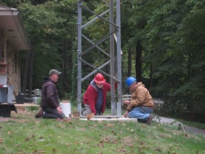
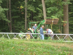
Once the antennas were all assembled the next step was to complete the assembly of the tower.  This included bolting the tower sections together installing the large step bolts on one leg of the tower.  The tower sections were quite heavy so I had to use my tractor to move them into position.


Don Assembling Control Box

Don Assembling Control Box


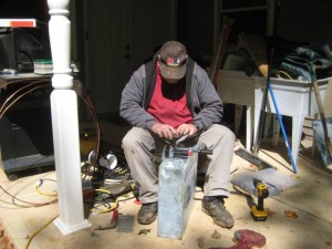
Once the tower was assembled we had to move on to the construction of the control box and coax jumpers.  The Control box contained two Ameritron remote coax switches, and lighting protectors for each of the incoming feedlines and the rotor lines.  The box is bolted to the tower and has a ground conductor that is connected to tower ground system which consists of 6 ground rods.


Control Box

Control Box


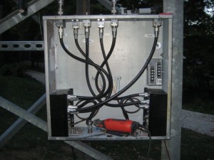
The partially completed control box was attached to the tower after the tower was erected.  The six lightning arrestors are the bulkhead type mounted to the top of the control box.  An “O” ring and stainless steel washer was used to seal the hole where the lightning arrestor passes through the control box.  The small box on the mid-right side of the box is the protector for the rotor.  Only four of the 8 connections were required for my application.

Tower Showing new Rotor and Thrust Bearing Shelves

Tower Showing new Rotor and Thrust Bearing Shelves

The photo to the right shows the top of the tower with the rotor plate and two thrust bearing plates installed.  The rotor plate that came with the tower was made of 12 gage  sheet metal and was a bit too flimsy when you consider it would be supporting a heavy rotor and absorbing the torque of the heavy antennas and Chrome Moly mast.  I was fortunate enough to find a local machine show that was able to laser cut a new rotor mounting plate from 1/4″ steel plate. They also made new thrust bearing plates.

I think many of the cases where the bolts that hold the rotor in place work their way loose over time are probably caused by flexing of light gage rotor shelves.

In the next installment I will show the actual installation of the tower and antennas.

73,

Fred


My First Tower (Part 4)

Once the tower was selected I started the process of nailing down what antennas would be on  the tower.  Since I felt this would probably be the only tower I ever have installed, some of my key requirements were:

  1. Get the maximum band coverage from the antennas on the tower ( 40m thru 70 cm)
  2. The antennas had to have a good reliability history with a minimum of parts that might fail (traps or moving parts).
  3. Install long life feed-lines (hardline)
  4. An oversized rotor to reduce the risk of a rotor failure
  5. Chrome Molly mast
  6. 60-70′ self supporting tower
  7. Dual thrust bearings; so the rotor could be easily replaced without removing the antennas
  8. Only two feed-lines to the ham shack (switching required at the base of the tower in a weather proof enclosure)
  9. High quality lightening protection
  10. Select tower to withstand 110 mph wind without ice and a 85 mph with 1/2 inch of ice.

Ultimately the primary antenna I selected was an M2 10-30 LP8, 8 element log periodic, which  covers 30m to 10m.  For 40m I selected a Cushcraft XM-240 2 element yagi and for 6m, 2m and 70cm I selected a Cushcraft A627013S.

The rotor I selected was an M2 Orion 2800P w/o their controller.  I ordered a Green Heron RT-21 rotor controller.  The RT-21was recommended by Don, because he felt it was much more dependable than the Orion rotor control box.  The Green Heron control is fantastic!

Once the material list was completed and had been approved by Don, I began to place orders.  Some of the items had longer lead times than others.   As the materials arrived I marked them as having arrived on the Excel spreadsheet.  Once all of the materials had arrived it was time to construct the tower base.

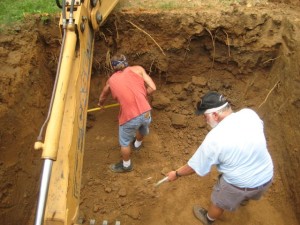
Digging the Hole

Digging the Hole


The 70′ Trylon Super Titan requires a large base.  I chose the pad and pier design from their design guidelines.  The pad is 10′ by 10′ x 2.5′ with a 5′ x 5′ x 5′ pier.  The base took nearly 16 yards of concrete.


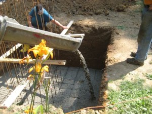
Pouring the Pad

Pouring the Pad


Once the 10′ x 10′ x 7′ deep hole was completed it was time to pour the pad.


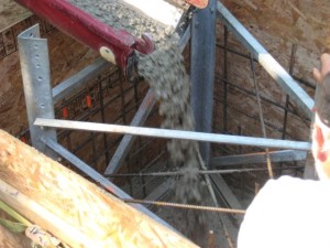
Pouring the Pad

Pouring the Pad


Once the pad was pour a second pour was made for the pier.


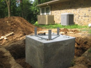
Completed Base

Completed Base

Once the forms were removed we got our first look at the mammoth chunk of concrete.


Base After Final Grade

Base After Final Grade

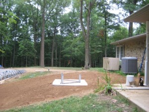
The final step was to use a use a motorized soil compactor to pack the soil tightly against the base.  This was followed by a final grade and grass seed.  The tower base was sprayed several times a day to assist in the curing.  The base then had to wait thirty days before the tower could be installed.

In the next installment well move into the antenna assembly and tower installation.

Until next time.

73,

Fred