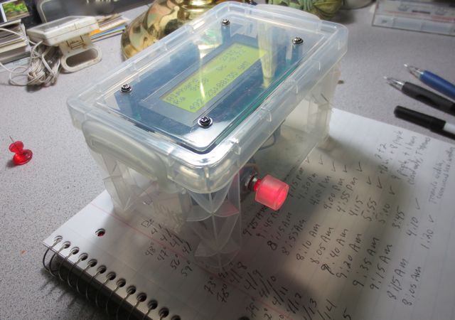
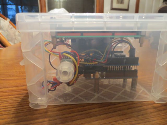
Top view of the Hour Angle Calculator in Operation — note the rotary encoder has an internal RED led.
I have been continuing to work with the Arduino single board computers. One of the tasks required at the Link Observatory is to align the Argo Navis (digital encoders) using two well spaced stars. My wife and I have found that the easiest way to pinpoint the alignment stars is to use the telescopes German equatorial mounts setting circles. One of the challenges we had using the setting circles was having to continually recalculate the Right Ascension Hour Angle as we are moving the telescope into position–it takes a bit a time to accurately position a 36″ telescope that weighs over a ton. Therefore we would have to keep recalculating the hour angle which is calculated by subtracting the stars Right Ascension from the current local Sidereal time ( which is obviously changing).
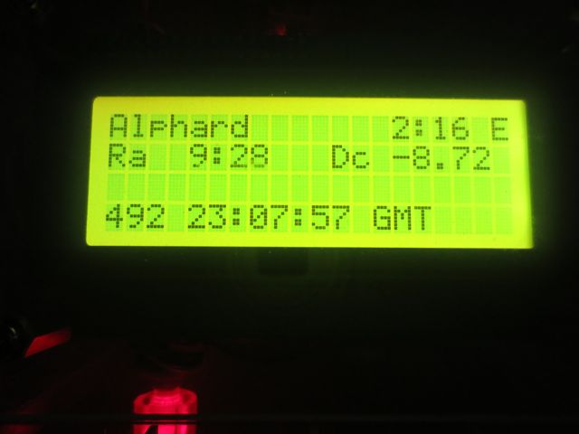 I decided to use an Arduino to continuously calculate the RA Hour Angle using equations to calculate the sidereal time and the Hour Angle given the selected alignment stars Right Ascension. This project involved building a circuit which included a real time clock, a rotary encoder ( to select the star from a lookup table) and an LCD display. I assembled the circuit in a plastic 3″ x 5′ card box I found at Office Depot.
One of the more challenging aspects of the design for me was getting the rotary encoder to accurately count. I used a 24 pulse per rotation encoder which I purchased from Sparkfun (http://sparkfun.com). In the initial circuit the software would count extra pulses and sometimes miss pulses. After I tried several different software schemes to resolve the problem I finally used an oscilloscope to examine the waveforms coming out of the rotary encoder. Once I attached the scope I immediately saw the problem. When the encoder is being rotated It would frequently have high frequency wiping noise on the encoder A and B pins. After I attached a couple of .01 uf capacitors between the pins and ground the encoder began working flawlessly.
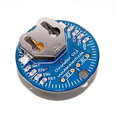
ChronoDot Realtime Clock Module
The next challenge was to interface a realtime clock to the Arduino. This turned out to be very easy using a ChronoDot clock module. This little gem interfaces to the Arduino using the I2C serial interface. It will run over 8 years on a single battery and will maintain the time with an accuracy 1 minute a year. The module requires four connections (5V, Gnd, SCL and SDA). SCL and SDA are the serial interface connections. The neat thing about the I2C interface is that many devices can share the same interface. In this project I also used the I2C interface to interface a 4 line by 20 character display.
 I spent quite of bit of time developing the software–mainly because I was also learning how to program in ‘C’ at the same time I was developing the code to for the project.
The software to interface to the realtime clock, rotary encoder and display were developed by modifying examples readily available on the web.
I also had to develop the software to calculate the Sidereal time from GMT using one of several algorithms I found on the web. One problem I experienced was an error of about 5 to 30 seconds in the Sidereal time because of floating point round off errors in the Arduino software. This occurs because the Arduino software does not support double precision floating point calculations. This did not present a major problem in my application since the resolution of the mechanical setting circles on the Link Telescope only have a precision of around 1 minute.
The following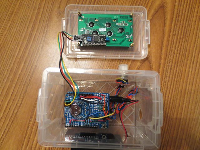 photo shows the internal circuitry of the Hour Angle Calculator. The circuit board at the top of the photo is the backside of the 4 line by 20 character display. The four wires connect the display to power and the I2C interface. The circuit board shown in the 3 x 5 file card box is the prototyping shield attached to the top of the Arduino. This board holds the realtime clock, the pull-up resistors and bypass capacitors for the rotary encoder and other wiring to needed to interface to the Arduino. The circuit can be powered for several hours using a 9V battery.
73,
Fred