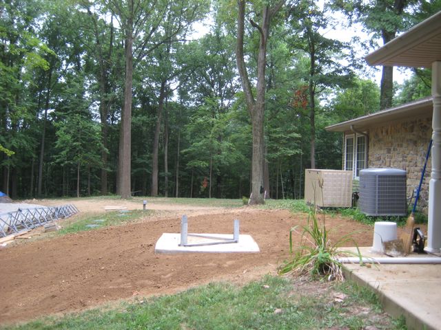
Base After Final Grade
After the tower base was completed it had to cure for at least 30 days before the tower could be installed. In my case that was not a problem, because the tower based was allowed to cure for about 6 weeks while I waited for one of the antennas and a few remaining hardware items to arrive.
Finally by mid September everything had arrived. It was now time for the big event. Don said that I should plan on a full week for the installation because several things had to be completed during that week prior to erecting the tower and antennas. Some of the major items that had to be completed were:
- Construct the three antennas and position them on the ground where they could be picked by the crane.
- Cut and terminate the 5 runs of Heliax that would be going up the tower
- Bolt the 7 tower sections together and install the step bolts up one side of the tower.
- Fabricate and install a stronger rotor plate, and an additional thrust bearing plate.
- Construction of the tower control box which holds the lightning protection and antenna switching.
- Construct the coax jumper loops which connect each antenna to its corresponding Heliax.
- Install the two thrust bearings on the tower
- Anchor the antenna mast inside the tower and install a large anchor at the top of he tower so that a come-along can be used the raise the mast as antennas are installed.
- Do a final check on the rotor before lifting the tower.
- Weather proof all connections on the antennas
- Tripple check every item that will be installed on the tower, including: antennas, rotor, bearings, rotor cable etc. It is much easier to fix an item when it is sitting on the ground than once it is 70′ in the air.
This list shows the major items that had to be completed before the tower could be installed. I left out a few of the items; including a half dozen trips to the hardware store to pickup a few odds and ends including over 20 saw horses to hold the antennas during assembly.
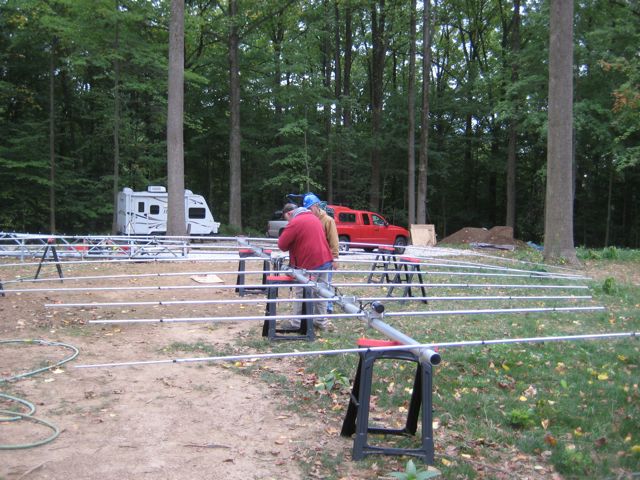
Assembly of M2 10-30LP8
Assembly of the antennas was a much bigger job than I had anticipated. One of the first steps is to find an area big enough to build two large beams so that they can be picked up by the crane.
This was not an easy task since there were still a number of large trees remaining in the backyard.
We started with the M2 10-30 LP8 which has a 30 ft boom and 8 elements with the longest being 55 feet tip-to-tip. It is important to carefully read and follow the instructions and re-check all the work at least two times. A final step was to check the antenna with an antenna analyzer (MFJ-259B) to make sure it was performing like an antenna (low SWR an resonant at all the right frequencies). The assembly of the LP8 took 1-1/2 long days. The XM240 took another day to assemble. The small 2m, 6m and 70cm multi-beam only took a couple of hours to assemble.
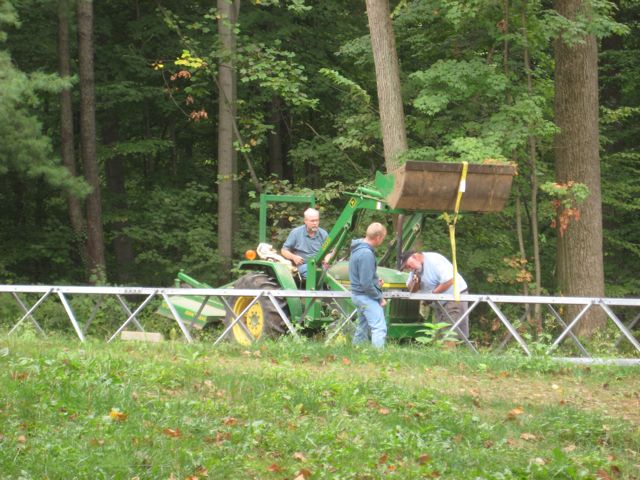
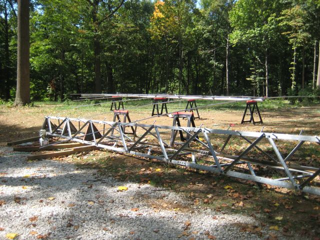
Assembling Tower Sections
Once the antennas were all assembled the next step was to complete the assembly of the tower. This included bolting the tower sections together installing the large step bolts on one leg of the tower. The tower sections were quite heavy so I had to use my tractor to move them into position.
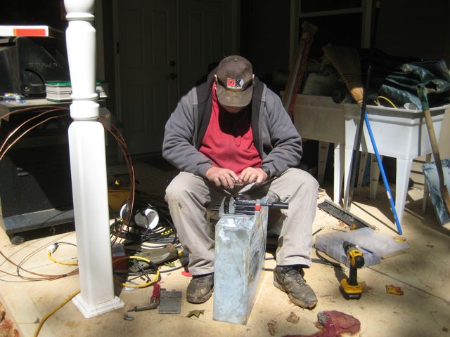
Don Assembling Control Box
Once the tower was assembled we had to move on to the construction of the control box and coax jumpers. The Control box contained two Ameritron remote coax switches, and lighting protectors for each of the incoming feedlines and the rotor lines. The box is bolted to the tower and has a ground conductor that is connected to tower ground system which consists of 6 ground rods.
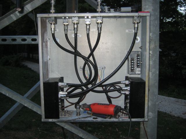
Control Box
The partially completed control box was attached to the tower after the tower was erected. The six lightning arrestors are the bulkhead type mounted to the top of the control box. An “O” ring and stainless steel washer was used to seal the hole where the lightning arrestor passes through the control box. The small box on the mid-right side of the box is the protector for the rotor. Only four of the 8 connections were required for my application.
Tower Showing new Rotor and Thrust Bearing Shelves
The photo to the right shows the top of the tower with the rotor plate and two thrust bearing plates installed. The rotor plate that came with the tower was made of 12 gage sheet metal and was a bit too flimsy when you consider it would be supporting a heavy rotor and absorbing the torque of the heavy antennas and Chrome Moly mast. I was fortunate enough to find a local machine show that was able to laser cut a new rotor mounting plate from 1/4″ steel plate. They also made new thrust bearing plates.
I think many of the cases where the bolts that hold the rotor in place work their way loose over time are probably caused by flexing of light gage rotor shelves.
In the next installment I will show the actual installation of the tower and antennas.
73,
Fred