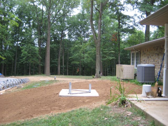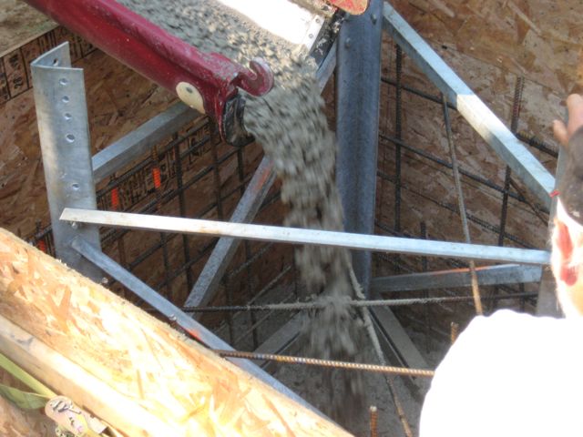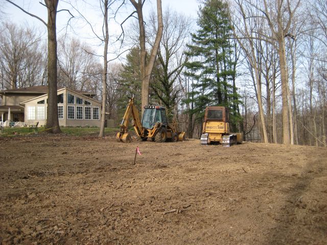
After a year of planning and preparation it was finally time to install the tower. The previous 5 articles focused on the preparations that led up to installation day.
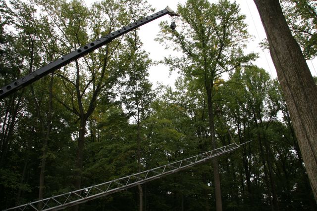
Crane Lifting Tower
Don, K4ZA, would be using a crane for the tower installation. The first step was to lift the assembled tower into position and bolt it to the concrete base. This took a fairly tall crane because the tower was 70′ tall and the crane was sitting nearly 10′ lower than the tower base. Don selected a 100′ crane with an additional 20′ Jib. Fortunately the crane operator did not have install the jib because that would have added a couple of hours to the time onsite. The photo at the right shows the crane beginning to lift the tower.
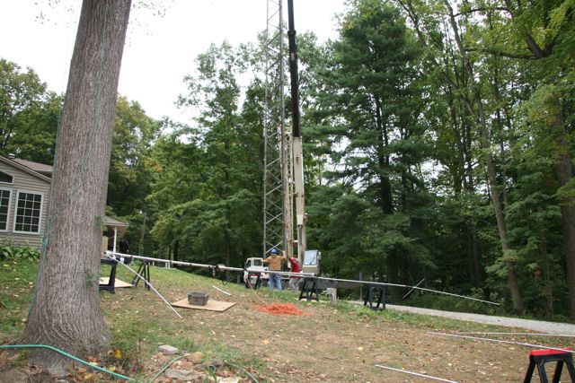
Tower Being Positioned Over Base
Once the tower was fully vertical, the crane operator eased it over the concrete base so that the ground crew could attach the tower to the Trylon base section.
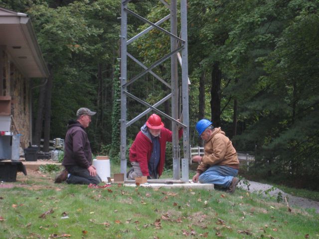
Once the tower was aligned to the base, twelve bolts were used to attach it to the base. Once the tower was secured to the base Don climbed up the tower to begin the installation of the antennas.
The procedure to install the antennas involved installing the highest antenna first, followed by the next highest and finally installation of the lowest antenna. After each antenna was attached to the mast, the mast was raised using a come-along which had been attached between the lower portion of the chrome-molly mast and the top thrust bearing plate at the top of the tower.
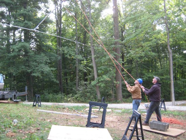
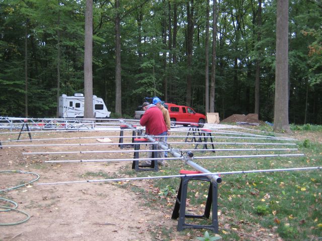
Lifting XM-240
Since highest antenna was the small Cushcraft 2m, 6m and 70cm antenna it was decided it would be easier to install the XM-240B (2 element 40m beam) first. The photo to the right shows the ground crew guiding the 40m beam as the crane operator lifted it to Don. Our job was to keep it properly aligned so that Don could pull it to the mast and an install the U bolts.
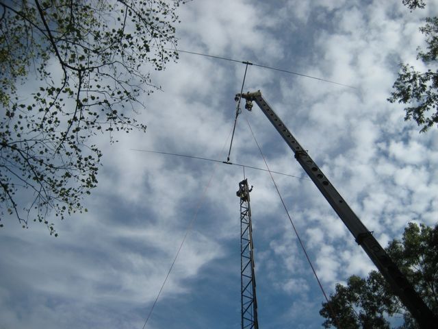
XM-240 Being Lifted Into Position by the Crane
The next two photos show the 40m beam being lifted into position and Don attaching the beam to the mast.
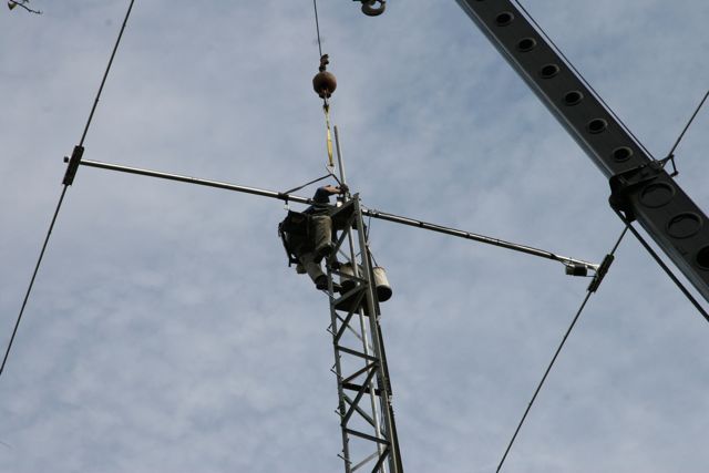
Attachment of the 40m Beam to the Mast
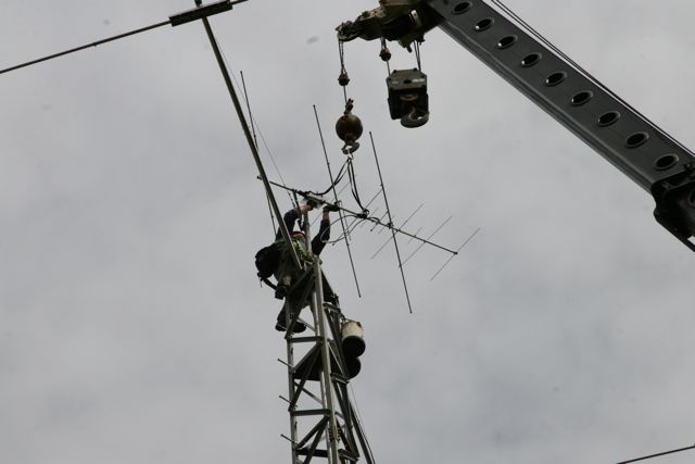
Installing 2m, 6m and 70cm Beam
Once the 40m beam was in place, the small Cushcraft beam was attached above the 40m beam.

Installing M2 10-30 LP8
The final antenna we lifted was the monster 8 element 10-30 mHz M2 log periodic. The log periodic has a 30 foot boom and a maximum element length of 55 ft. We experienced a lot of excitement lifting this antenna because one of the elements slipped behind the chain on the crane boom when it got hit by a gust of wind. It took several minutes to maneuver the beam out of the chain. I think my heart stopped for a few seconds until the LP8 popped out of the crane chain.
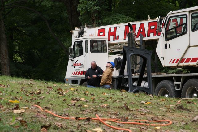
Settling up with the Crane Operator
After all of the antennas had been attached to the mast it was time to pay the crane operator and get him on his way. Time is literally money when you are dealing with cranes.
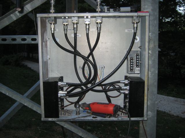
After the crane work was completed Don spent a couple more hours finishing the antenna and rotor installation. The Heliax, rotor cable and weather proofing of all of the connectors were completed the next day.
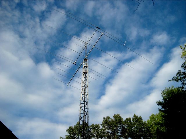
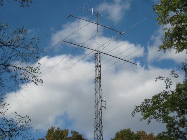
Completed Tower and Antennas
After everything was done we celebrated with a nice steak dinner!
73,
Fred